Hydraulic AC Servo System for Industrial Press and Injection Molding
Electro-Hydraulic Servo Drive Technology

Hydraulic AC Servo System Engineering Guide: Technical Selection, Energy ROI Calculations, Retrofit Paradigms & Global Procurement Trends (2026–2030)

Empowering plant engineers and global machinery OEMs with high-dynamic closed-loop servo pump control. Cut power consumption by 30% to 70%, achieve ±0.1 bar pressure accuracy, and extend hydraulic fluid service life across heavy industrial applications.

Up to 70%Energy reduction vs fixed displacement
< 20 msPressure dynamic response time
±0.1 BarClosed-loop pressure control precision
25+ YearsLubi automation engineering authority
Technical Architecture & Fundamentals

Demystifying the Modern Hydraulic AC Servo System

How closed-loop electro-hydraulic integration replaces energy-intensive proportional valve throttling with instantaneous vector-controlled brushless permanent magnet motor torque.

Core Physics & Operating Principle

Traditional hydraulic systems utilize induction motors running at a constant nominal velocity (1450–1750 RPM) driving fixed-displacement vane or gear pumps. Fluid volume and system pressure are regulated by bypassing excess oil back to the hydraulic reservoir through relief and proportional valves—converting electrical power directly into wasted thermal energy.

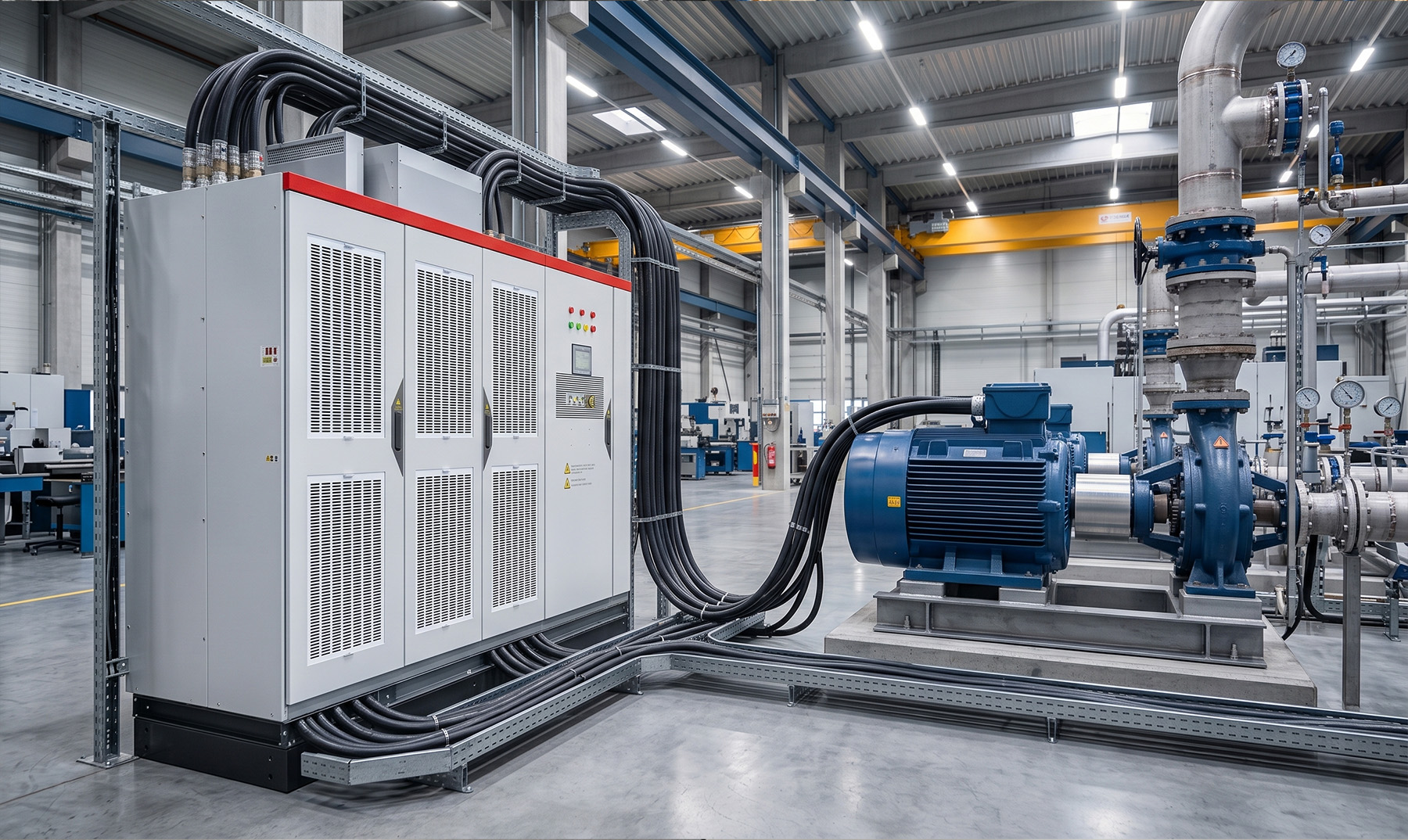
A high-performance Hydraulic AC Servo System fundamentally restructures this dynamic. By combining a Permanent Magnet Synchronous Motor (PMSM), a high-frequency response AC Servo Drive, a specialized low-pulsation Internal Gear Pump, and high-precision pressure transducers, power is delivered strictly on demand.

  • 01

    Dynamic Speed & Torque Modulation

    Flow rate (Q) is directly proportional to motor rotational speed (N × V displacement), while system pressure (P) is proportional to motor output torque (T = P × V / 20π). The drive dynamically modulates RPM from 0 to 3000+ RPM in milliseconds.

  • 02

    Zero-Throttling Holding Phase

    During holding pressure and dwell cycles, the servo motor reduces rotation to nominal trickle speeds (10–50 RPM) strictly required to offset internal pump leakage—reducing holding energy consumption by up to 90%.

  • 03

    Microsecond Dual-Loop Control

    Advanced DSP algorithms execute embedded pressure-flow (P/Q) transition loops, seamlessly switching between velocity control (acceleration/rapid traverse) and torque control (clamping/forming) without pressure spikes.

Lubi Electronics hydraulic servo application engineers configuring servo drives
±0.1 BarHigh precision pressure repeatability
Engineered Product Lines

Lubi High-Performance Hydraulic AC Servo Recommendations

Factory-tested, modular servo-pump packages tailored for high-duty injection molding, precision metal stamping, CNC bending, and heavy hydraulic forging presses.

Lubi Servo System for Plastics Machinery
Plastics & Rubber

Lubi HydroServo Series-I: Injection Molding Optimized

Designed specifically for plastics injection molding machines (90T to 3000T clamping force). Features ultra-low rotational inertia PMSM motors paired with high-pressure internal gear pumps (up to 280 bar peak).

  • • Motor Power: 7.5 kW – 110 kW per single drive module
  • • Max System Pressure: 17.5 MPa / 25.0 MPa option
  • • EtherCAT & CANopen motion control onboard
  • • Multi-pump confluent control for high-tonnage machines
Heavy Metal Stamping Hydraulic Servo Drives
Forging & Metal Forming

Lubi HydroServo Series-H: Heavy Industrial Forging & Presses

Built for harsh shock loads and extreme pressure profiles found in automotive metal stamping, deep drawing, and powder metallurgy hydraulic presses.

  • • Torque Output: Up to 1200 Nm continuous / 3000 Nm peak
  • • Master-Slave Synchronous Multi-Motor Array (up to 600 kW)
  • • Heavy-duty overload capacity: 250% for 5 seconds
  • • Integrated oil temperature & vibration sensor logging
Precision CNC Bending Machine Servo Unit
Precision Tooling

Lubi HydroServo Series-P: CNC Press Brake & Bending Packages

Micro-meter displacement accuracy for multi-axis CNC press brakes. Delivers rapid acceleration and silent operation (< 62 dB(A)) during bending cycles.

  • • Position Repeatability: ±0.005 mm with linear scale feedback
  • • Dual-stage P/Q decoupling algorithm
  • • Compact drive footprint for space-constrained panels
  • • PROFINET RT / IRT & Modbus TCP fieldbus connectivity
Information Gain & Performance Benchmarking

Hydraulic Drive Technologies: Comparative Matrix

An exhaustive engineering comparison validating why global OEMs are transitioning from variable displacement and all-electric architectures to modern Hydraulic AC Servo Systems.

Performance Parameter Fixed Displacement + Induction Motor Proportional Valve + Variable Pump All-Electric Mechanical Servo Drive Lubi Hydraulic AC Servo System
Average Energy Efficiency Low (30% – 45%) Moderate (50% – 65%) Very High (85% – 92%) High to Extreme (75% – 88%)
Initial Capital Expenditure (CapEx) Baseline (Lowest) 1.3x Baseline 2.8x – 4.0x Baseline 1.4x – 1.8x Baseline (Payback < 12 mo.)
Pressure Control Precision Poor (±3.0 – 5.0 bar) Moderate (±1.0 – 2.0 bar) N/A (Load cell dependent) Ultra-Precise (±0.1 – 0.3 bar)
Pressure Response Time Slow (100 ms – 250 ms) Medium (60 ms – 120 ms) Fast (< 15 ms) Ultra-Fast (15 ms – 30 ms)
Hydraulic Oil Heat Generation Extreme (Chiller required) High (Chiller required) Zero (No fluid) Minimal (ΔT < 5°C/hr, Chiller downsized)
Acoustic Emission / Noise Level High (78 – 85 dB(A)) Moderate (72 – 78 dB(A)) Silent (< 65 dB(A)) Ultra-Quiet (58 – 68 dB(A))
Maximum Force / Tonnage Density High High Limited in high tonnages Unlimited (Multi-pump confluent blocks)
Technology Evolution (2026–2035)

As global manufacturing transitions toward Industry 4.0, zero-carbon factories, and localized smart manufacturing, Hydraulic AC Servo Systems are undergoing four key technological shifts.

1. Decentralized Electro-Hydraulic Actuation (EHA)

Migration from centralized hydraulic power units (HPUs) with extensive piping toward self-contained, pipe-free servo electro-hydraulic linear actuators. EHA units eliminate external hose leakages, dramatically reduce fluid volume by up to 80%, and enable plug-and-play machine assembly.

2. AI-Driven Predictive Fluid Analytics & Edge Monitoring

Integration of MEMS vibration, acoustic spectroscopy, and optical oil degradation sensors directly into the servo drive logic block. High-frequency digital twin models analyze pump micro-wear, dynamic fluid viscosity shifts, and cavitation risks in real time, shifting maintenance from reactive to predictive.

3. Silicon Carbide (SiC) Power Inverters

Next-generation hydraulic AC servo drives incorporate Wide Bandgap (WBG) SiC MOSFET power modules. This innovation achieves switching frequencies exceeding 30 kHz, lowers drive thermal dissipation by 40%, footprint by 35%, and optimizes dynamic current responsiveness under fast load transitions.

4. Bio-Based Synthetic Fluids & Zero-Leakage Sealing

The convergence of low-viscosity biodegradable synthetic esters with optimized internal gear pumps running high volumetric efficiency at low RPM. This trend allows hydraulic servo systems to operate cleanly in food-grade, pharmaceutical, and high-hygiene cleanroom environments.

Procurement Strategy

How international procurement directors, OEMs, and EPC contractors are reshaping hardware selection criteria to mitigate supply chain volatility and satisfy stringent ESG mandates.

TCO Sourcing Paradigm

1. Shift from Initial CapEx to 10-Year Total Cost of Ownership

Leading global buyers no longer evaluate hydraulic systems solely on initial purchase price. Operating electricity accounts for over 75% of a hydraulic machine’s lifecycle cost over ten years. Hydraulic AC Servo Systems deliver a verified ROI payback period within 8 to 14 months, making them the default spec for greenfield investments and factory modernizations.

Formula: TCO = CapEx + Energy Cost (kWh × Rate × Hours) + Maintenance & Oil Disposal Cost - Residual Salvage Value.

Regulatory Compliance

2. Stringent EU ErP Directive & Carbon Border Adjustments (CBAM)

With multinational export mandates enforcing carbon footprint tracking across Tier-1 and Tier-2 supply chains, machine builders MUST certify energy efficiency metrics. Servo-hydraulic equipment reduces Scope 2 indirect carbon emissions per manufactured component, ensuring uninterrupted access to European, American, and East Asian markets.

Modular Turnkey Supply

3. Single-Source Modular Power Assemblies (TTA Standards)

Procurement teams are actively consolidating vendors—moving away from buying motors, drives, pumps, and manifolds from separate suppliers. Buyers demand pre-commissioned, Type-Tested Assemblies (TTA) with fully documented pressure-flow validation, factory acceptance test (FAT) certification, and single-point engineering accountability.

Why Lubi Electronics

25+ Years of Industrial Automation & Servo System Manufacturing Rigor

Established in 1997, Lubi Electronics has evolved into a powerhouse of industrial control, medium voltage drives, type-tested control panel manufacturing, and advanced electro-hydraulic automation.

Our state-of-the-art manufacturing campus near Ahmedabad (Gujarat, India) combines in-house power electronics integration, surface-mount technology (SMT) lines, mechanical fabrication, and automated hydraulic test benches to ensure every servo pump system meets rigorous international standards.

  • 01

    Factory-Tested Pre-Commissioned Skids

    Every Lubi Hydraulic AC Servo unit undergoes 100% dynamic load testing, step-response analysis, and high-pressure fluid leakage audits prior to global dispatch.

  • 02

    Authorized Multi-Brand Integration Capabilities

    We combine our proprietary control panels and servo drives with authorized global components (Omron, Schneider, Nidec, Baumer, Advantech, Cognex) to deliver tailored OEM solutions.

  • 03

    30+ Global Sales & Service Engineering Centers

    Export customers benefit from dedicated application engineering, turnkey retrofit execution, remote commissioning support, and guaranteed fast-track spare parts availability.

Lubi Electronics advanced manufacturing plant and testing laboratory
100% FATDocumented routine testing for all orders
Global Buyer FAQ

Frequently Asked Questions on Hydraulic AC Servo Systems

Direct, highly technical answers to the most common queries submitted by global procurement managers, system integrators, and OEM engineers.

A Hydraulic AC Servo System integrates a High-Dynamic Permanent Magnet Synchronous Motor (PMSM), an AC Servo Drive, a high-efficiency internal gear pump or variable swashplate pump, and a high-speed pressure dynamic sensor. Unlike conventional hydraulic systems that run induction motors at constant speeds and throttle fluid via lossy proportional valves, a Hydraulic AC Servo System dynamically adjusts motor rotational speed and torque in real time to deliver exact fluid flow and pressure only when demanded. This eliminates idle throttling losses, reduces hydraulic fluid thermal degradation, and cuts power consumption by 30% to 70%.
Energy savings are achieved by eliminating proportional pressure-relieving throttle losses during holding, cooling, and idle phases. In conventional hydraulic press or molding cycles, the motor runs at 100% rated speed continuously, dumping unused pressurized oil back to the tank. In a Hydraulic AC Servo System, the AC servo motor decelerates to near zero RPM during pressure-holding and cooling stages, consuming minimal standby power (under 5% of nominal power). Energy is drawn only during active movement and pressure building.
Yes. Retrofitting involves replacing the constant-speed induction motor and standard vane or fixed-gear pump with a PMSM servo motor, specialized servo pump controller/drive, internal gear pump, pressure transducer, and updating the machine interface or PLC control logic. Lubi Electronics provides end-to-end application engineering for retrofits, including load profile analysis, pump/motor sizing calculations, mounting adapter design, panel integration, and commissioning.
Sizing requires analyzing four core variables: Maximum System Pressure (Pmax in bar or MPa), Maximum System Flow Rate (Qmax in L/min), Cycle Speed Demands (acceleration/deceleration response times in milliseconds), and Duty Cycle Duty Factor. These parameters determine pump displacement (cc/rev), peak/continuous torque (Nm) of the servo motor, drive current rating (A), hydraulic oil viscosity requirements, and thermal dissipation margins.
Hydraulic fluid heating is caused primarily by high-pressure fluid throttling across relief and proportional valves. Because an AC servo system controls flow by varying pump speed rather than restricting valve orifices, fluid shear stress and energy dissipation into the oil are drastically minimized. Oil operating temperatures typically decrease by 10°C to 20°C, preventing oil oxidation, extending seal lifespan, doubling oil replacement intervals, and allowing plants to downsize or eliminate auxiliary oil chillers.
Lubi Hydraulic AC Servo Systems support modern fieldbus protocols including EtherCAT, PROFINET, CANopen, Ethernet/IP, and Modbus TCP/RTU. High-speed protocols like EtherCAT enable microsecond-level synchronization between multiple motion axes, PLC master controllers, host SCADA platforms, and IoT edge devices for predictive health monitoring.

Ready to Modernize Your Hydraulic Machinery or OEM Line?

Consult with Lubi Electronics’ senior application engineers today. Send us your system cycle requirements, machine tonnage, pressure-flow curves, or load profiles for a precise technical recommendation, ROI calculation, and tailored quote.

Get a Quote